
Adding "Light Flare Kill Switch" on a Guitar
Adding Light Flare to kill switch Guitar. Upgrading Kill switch of your guitar.
A step by step guide that will light up a kill switch Guitar.
This is follow up of previous article where I showed you how to install Kill Switch on a Guitar. If you have not read it, here's the link to it: https://bit.ly/3QZfpnn
Well now that you have your Kill Switch ready, This guide will show you how to make it even cooler. You need to have decent soldering skills to follow along so make sure you are good with through hole P.C.B soldering. I also used few ply wood for temporary D.I.Y circuit board housing for the sake of its easy availability.
Pre Requisite
You need to be able to construct a circuit diagram into a solder-less bread board to follow along. Basic wood working skill is also required to house our circuit board.
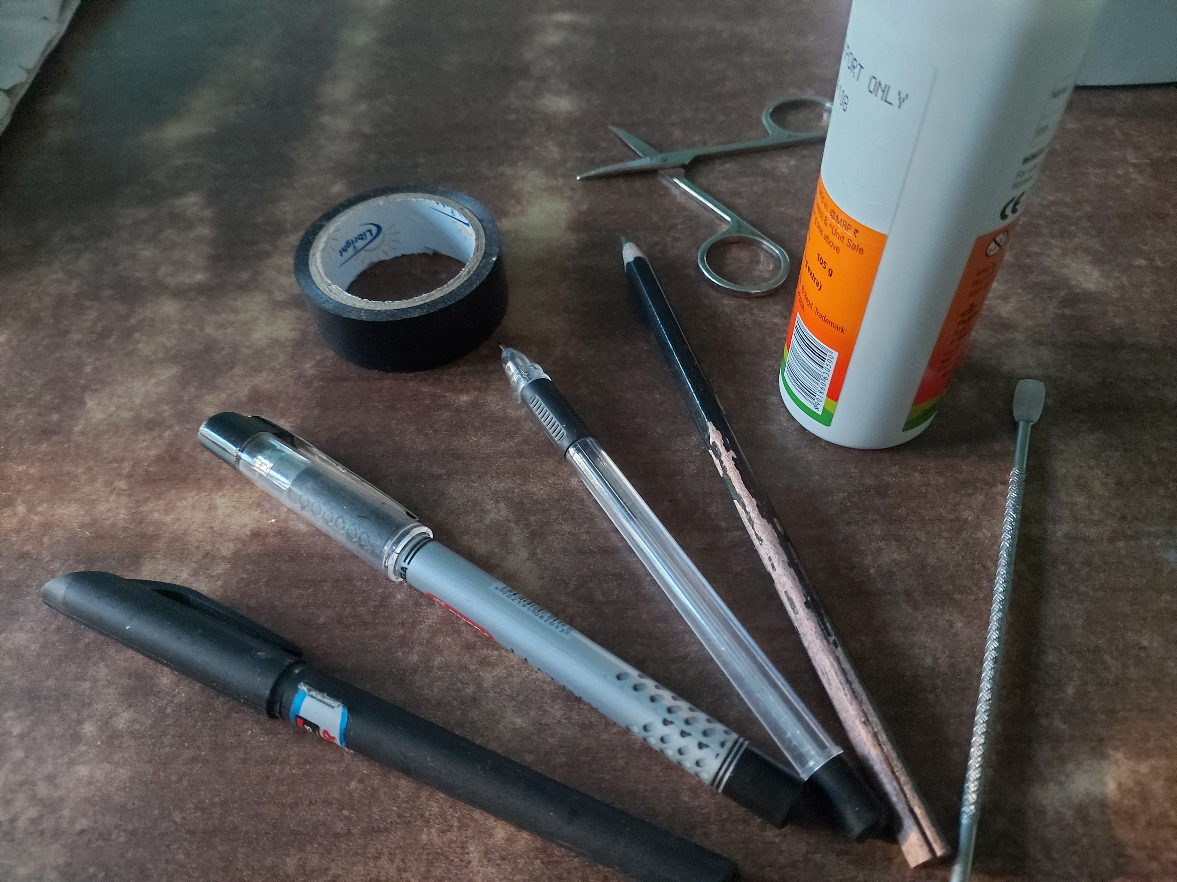
Required tools
- Wire clippers
- Multimeter
- Solder clipper
- screw driver
- duct tape
- a decent soldering iron
- a basic soldering flux
- pair of scissors
- momentary push button
- tweezers
- through hole circuit board (X2)
- two pin screw terminal (X8)
- AND gate IC
- NE 555 timer IC
- 14 pin IC base
- 8 pin IC base
- 9 Volts DC adaptor
- 100 Ohm resistor
- 10 Ohm resistor
- 220 Ohm resistor
- 1 Kilo Ohm resistor
- 10 nano Farad Capacitor
- 22 micro Farad Capacitor
- 1 Kilo Ohm resistor
- D.C jack plug
- D.C jack connector
- blue L.E.D
Instructions
We are going to separate this guide into three sections.
Dropping 9 Volts into recommended Vcc for AND gate IC
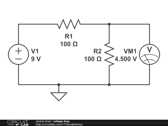
Connect two 100 Ohm resistors in series for recommended voltage drop. Connect wire from 2nd 100 Ohm resistor for connecting it to Vcc pin of AND gate. Before you connect to Vcc pin make sure your multimeter voltage rating shows 4.5 Volts with respect to ground terminal.
Installing button in our circuit to give variable input to our AND gate IC
We should expect our logic gate to give TRUE when we press button and FALSE when we release button. Refer to circuit diagram below to achieve this.
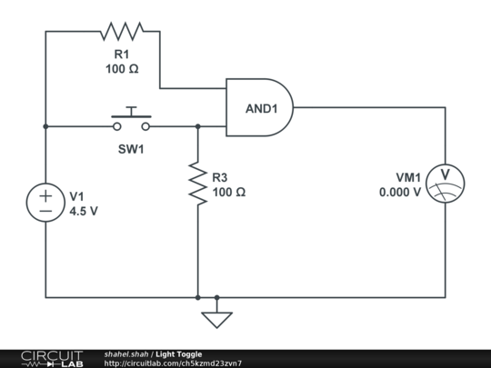
When SW1 is open circuited, this circuit gives you Zero Volts on output. When SW1 is closed circuited, the circuit gives you 5 Volts on output. Connect output of AND gate to pin 4 of NE 555 timer IC.
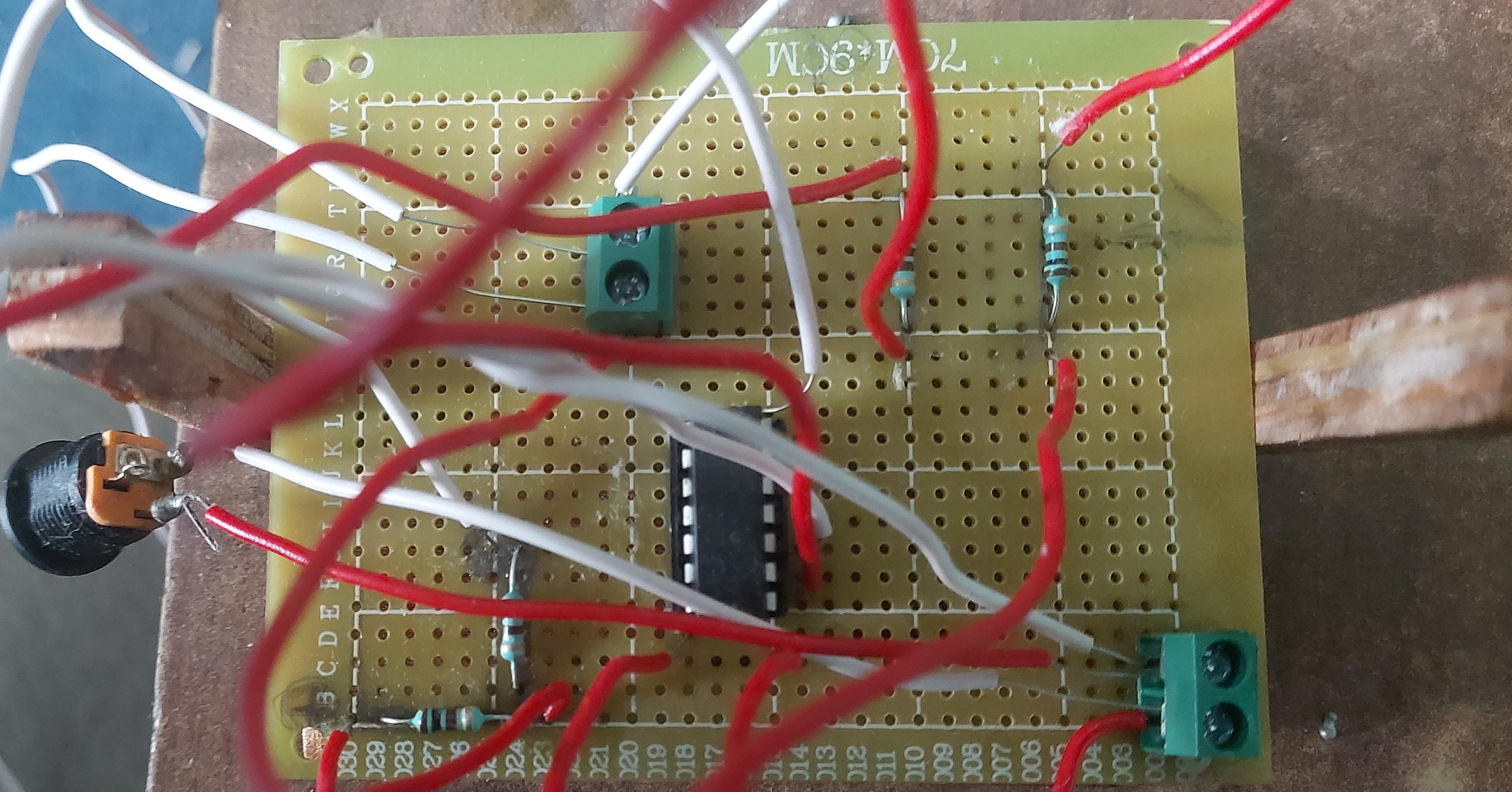
Connecting NE 555 timer IC in astable multivibrator mode
Construct NE555 timer IC according to above diagram. Connect 4.5 Volts into Vcc pin of NE 555 timer IC. Replace R1 with 220 Ohm resistor. Replace R2 with 1 Kilo Ohm resistor. Replace c with 22 micro Farad capacitor.
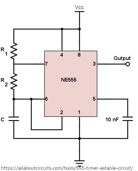
Twist positive terminals of 3 blue LEDs together.
Twist negative terminals of 3 blue LEDs together and connect a 10 Ohm resistor to this terminal using solder.
Connect positive terminal to pin 3 of NE 555 timer IC.
Connect negative terminal to ground.
Connect output of AND gate IC to pin 4 of NE 555 timer IC.
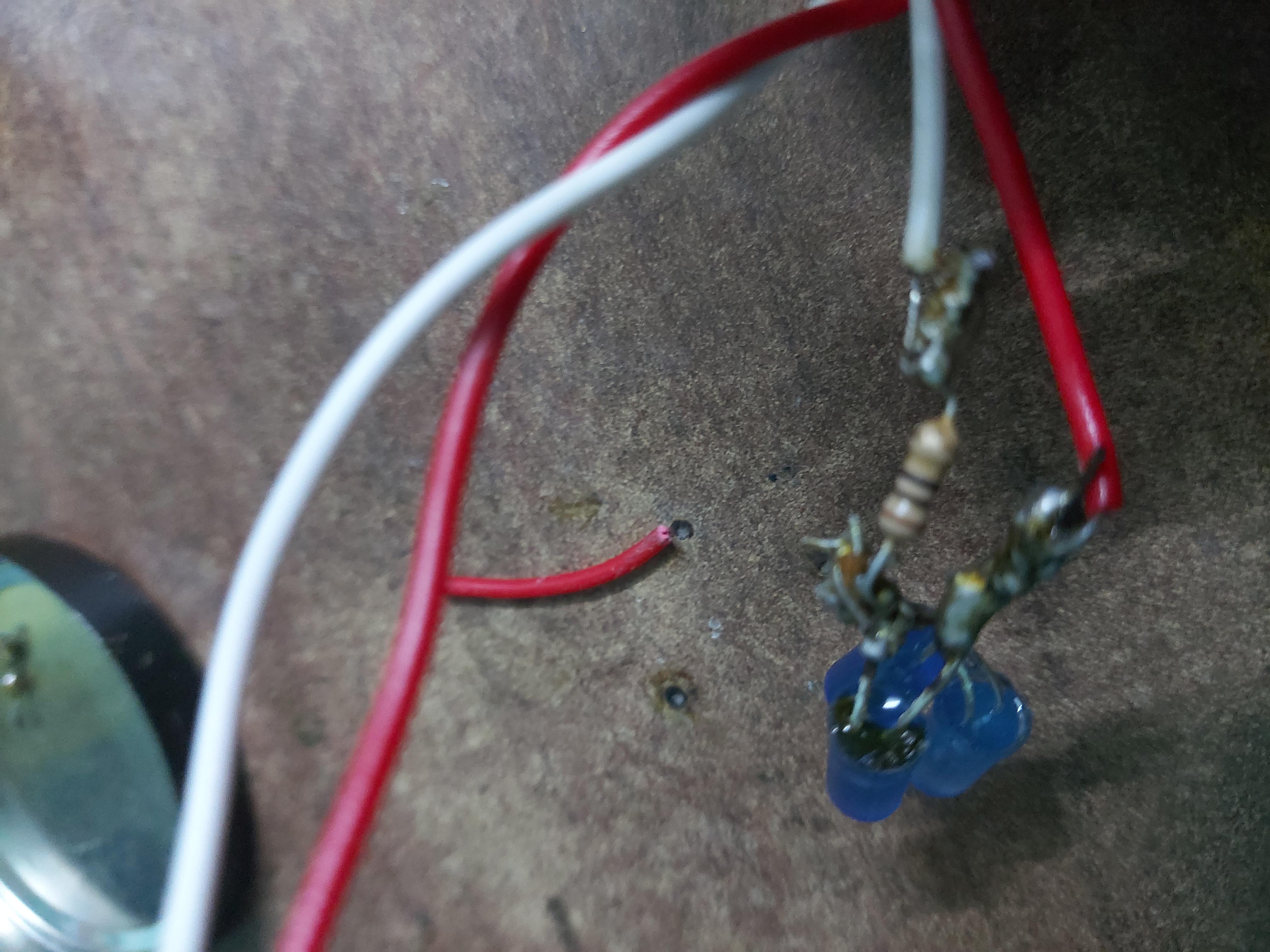
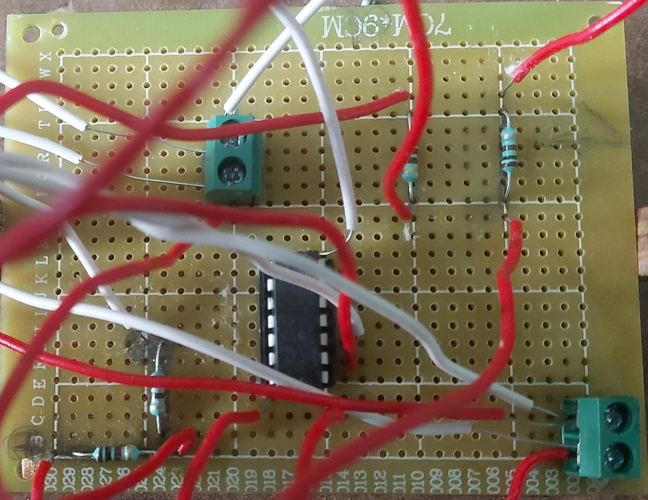
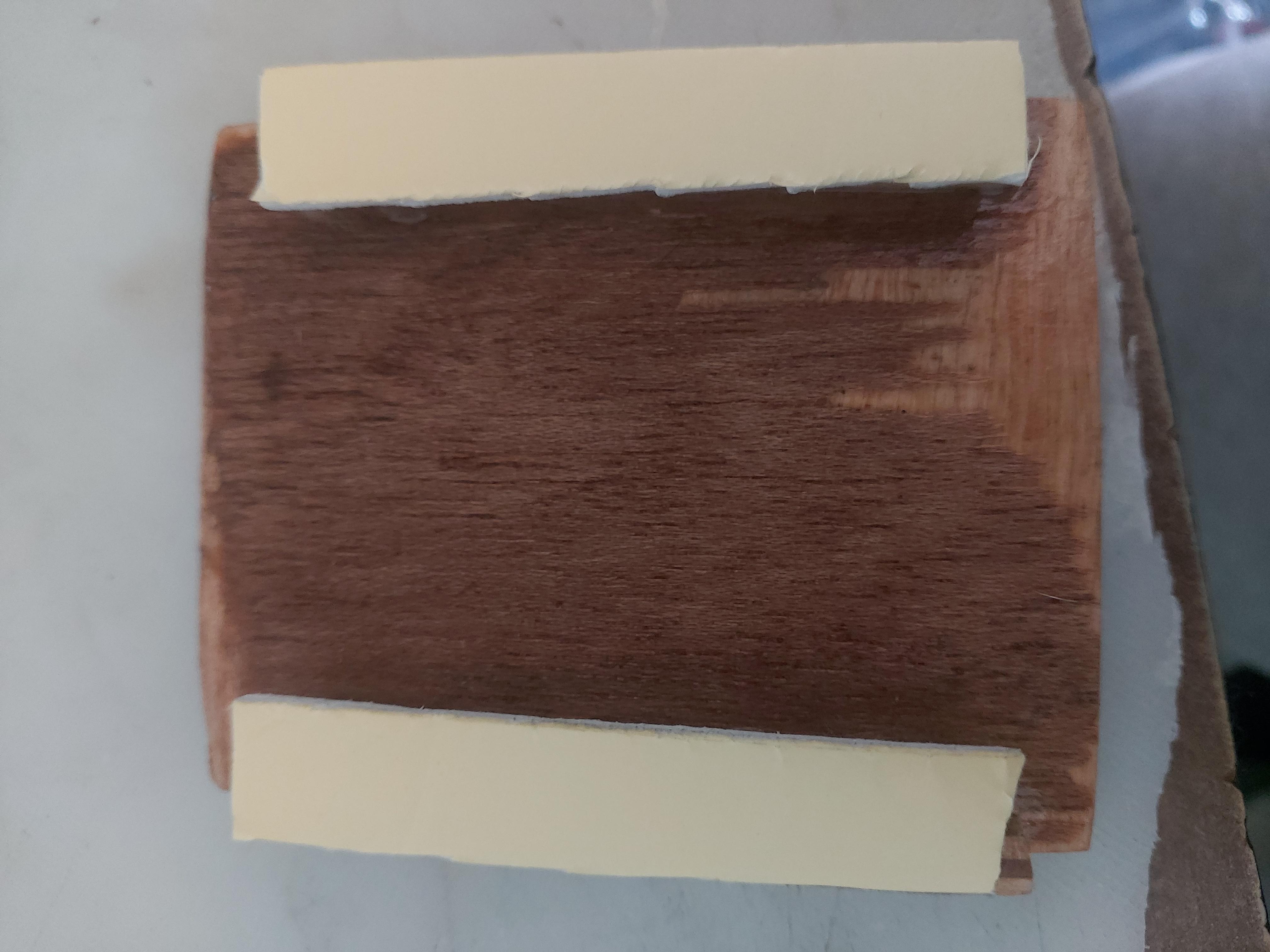
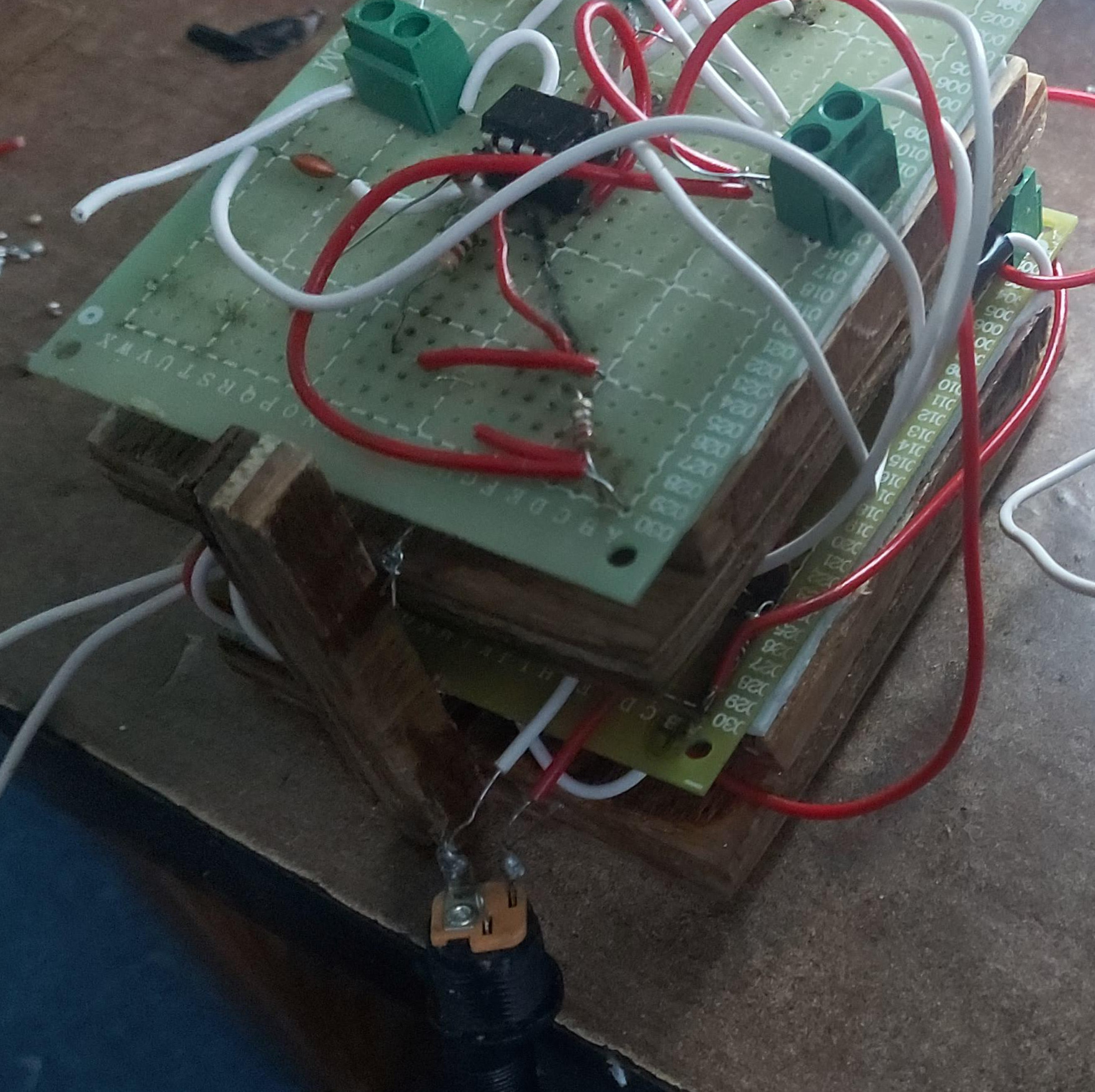
Circuit board housing
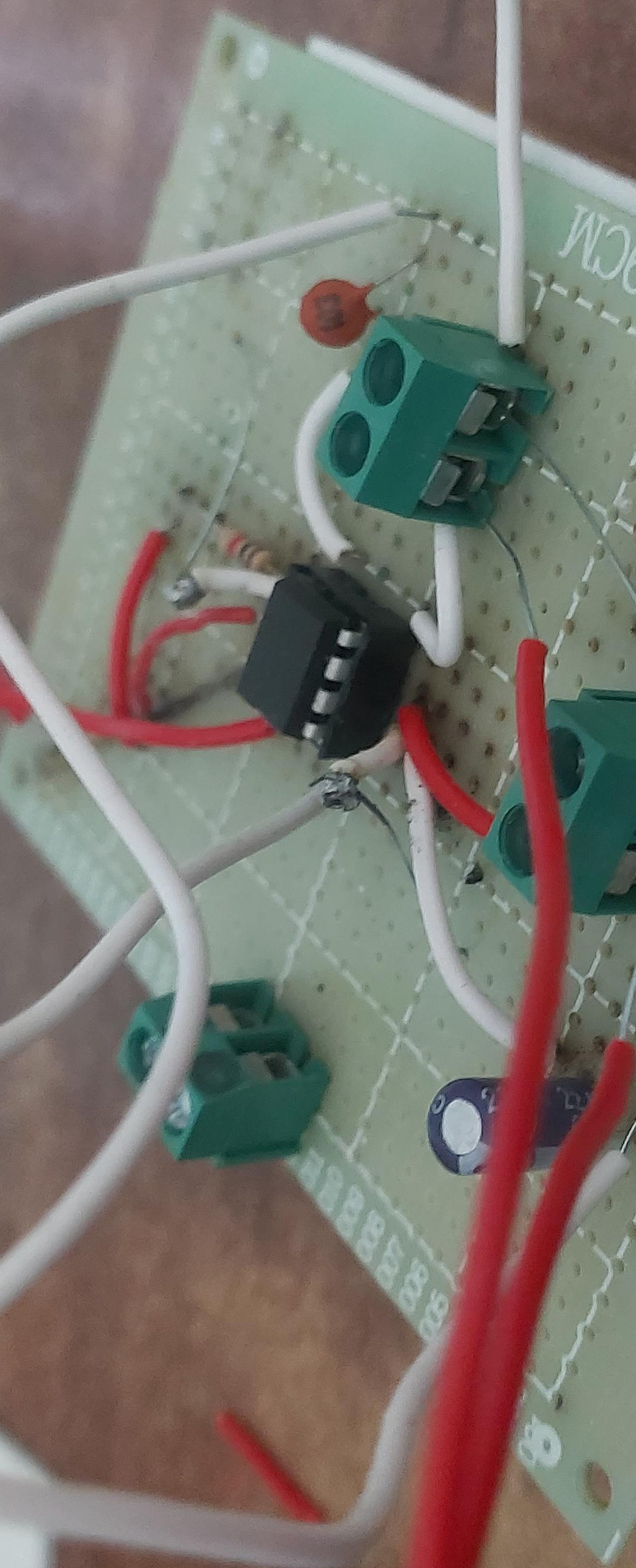
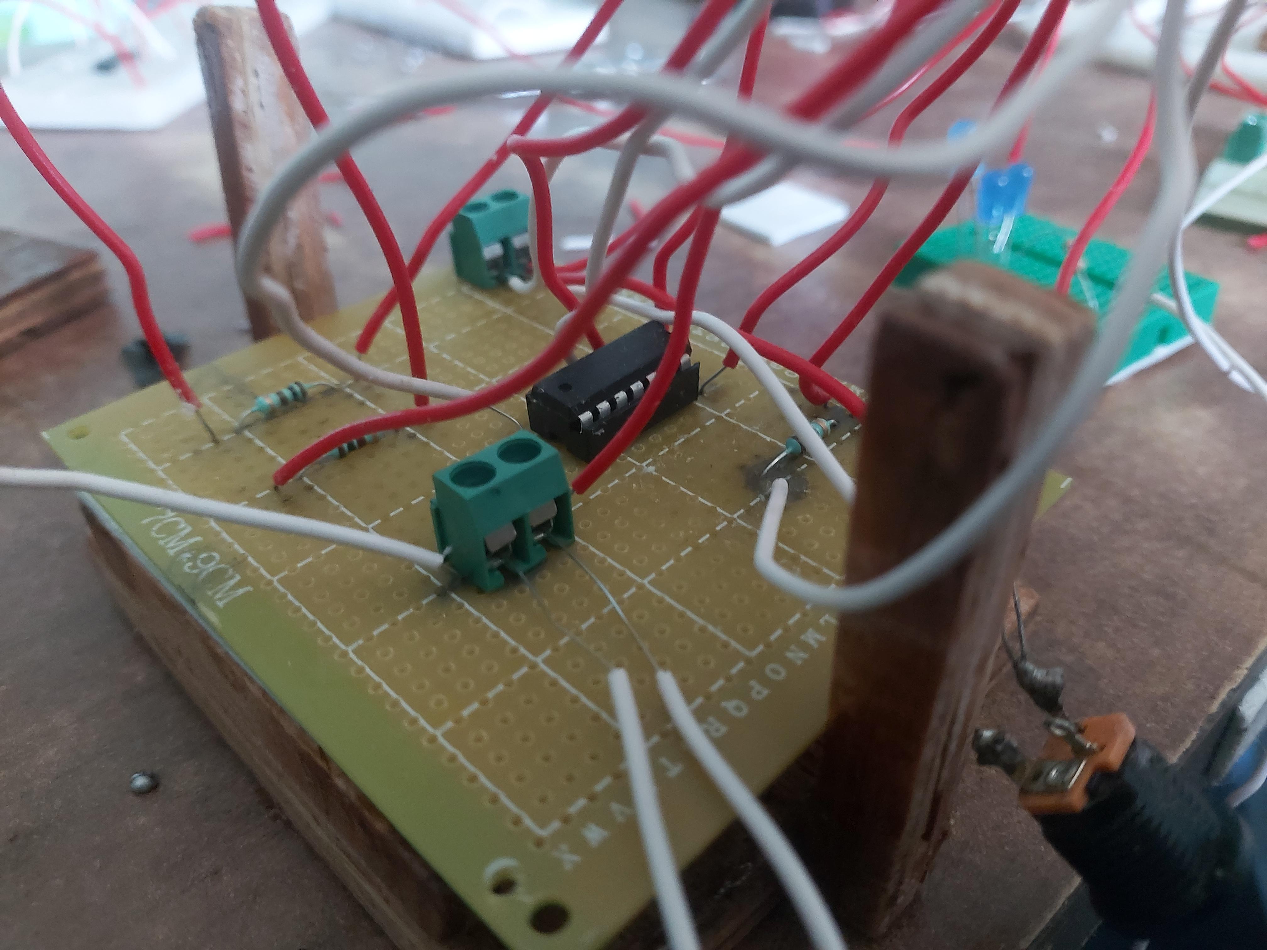
I used a 7X9 cm through hole Circuit board to house voltage drop circuit and AND gate IC circuit. I used another 7X9 cm through hole Circuit board to house NE 555 Timer IC.
Please refer to following images for creating temporary circuit board housing for cheap.
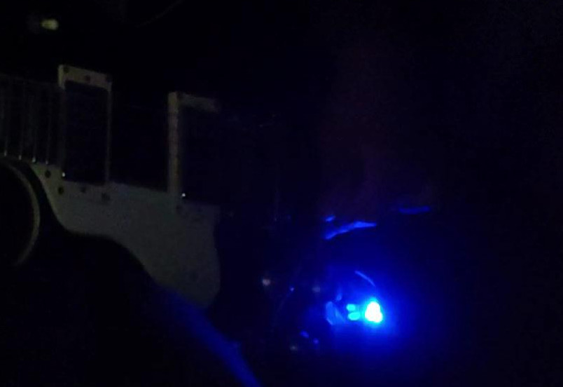
Installing AND gate switch on Guitar
Place toggle switch next to your kill switch and just like that, your Light Flare Kill Switch guitar customization is complete.
You might also like
Check out few other similar posts